USB Armory JTAG Interface
In the spring I made an attempt at creating a solderless JTAG breakout for the USB Armory. The design was flawed (I overlooked the VTRef signal) and trying to fix it caused the whole thing to fall apart. My next idea involved modifying an official enclosure to hold pogo pins aligned with the test pads but I decided against this as it required supplies not readily available. Ultimately, soldering seemed to be the best option at hand; as long as care is taken to avoid ripping off test pads, the process is mostly reversible.
The JTAG interface pinout is documented on the project wiki. Seven of the pads are typical JTAG signals, with the addition of MOD. The MOD port (alternatively named SJC_MOD in the i.MX53 Reference Manual) controls the operating mode of the System JTAG Controller (SJC). When negated (pulled low), all available TAPs are connected to the scan chain. This is the default mode, and will work with the i.MX53 target configuration provided with OpenOCD. Connecting to this pad should therefore be unnecessary, as the USB Armory ties this port to ground through a 4.7kΩ resistor. Attaching a floating wire to this pad apparently asserted the signal, which cost me about an hour of wondering why only the SJC TAP was available.
In order to protect the device and solder joints, I drilled tiny holes in an official case aligned with the test pads. These holes were just large enough to feed the insulated wire through so they provide a little bit of strain relief. I used a lead-based solder (at the cost of RoHS compliance) to lessen the temperatures required, and because the only lead-free solder on hand had a rosin core that leaves behind an unpleasant residue that would be difficult to wash away in this case. Solid core wire would have been ideal, but I had a colorful selection of (I think) 28 gauge stranded wire scavenged from an old serial cable. Lightly twisting and tinning the ends of the wire made things go smoothly.
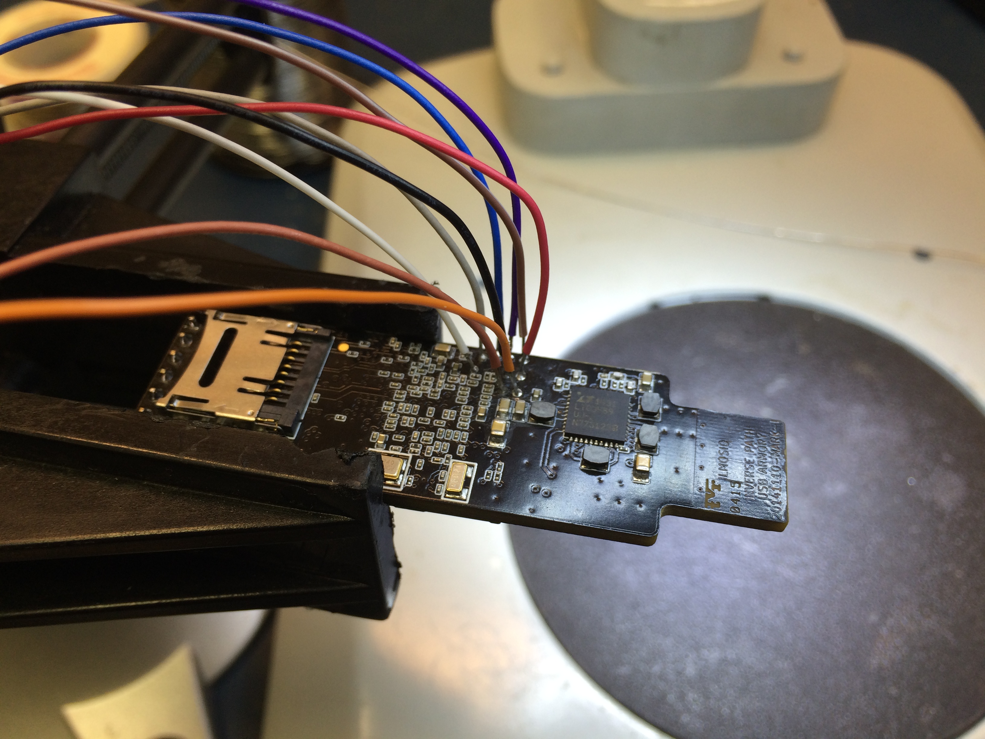 JTAG test pads with connections soldered
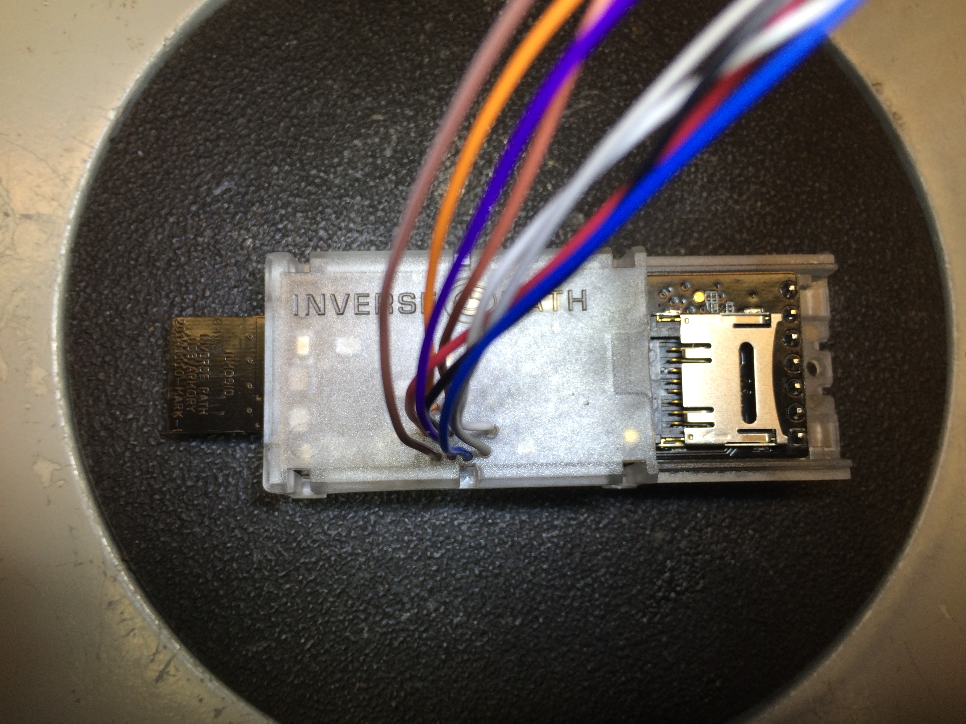 JTAG interface connections routed through official enclosure
I connected the JTAG leads to pin headers hastily and added some hot glue for strain relief. I left a bit of slack in the leads to possibly redo this in a cleaner way in the future. Where the leads route through the enclosure will probably receive a gob of hot glue in the future once I’m confident I don’t need to open it again.
The current setup works with OpenOCD, though there are still some issues to solve. While the boot ROM or U-Boot is executing the interface seems to work fine; I can halt the CPU and issue commands from the OpenOCD console. With the device booting into Linux however, multiple errors appear repeatedly:
Error: JTAG-DP OVERRUN - check clock, memaccess, or reduce jtag speed
Error: MEM_AP_CSW 0x80000042, MEM_AP_TAR 0x40001ff0
Error: Can't detect imx53.cpu's dbgbase from the ROM table; you need to specify it explicitly.
The low 16 bits of the MEM_AP_TAR value are not consistent. Another error appears occasionally:
Error: Can't read component with base address 0x40001000, the corresponding core might be turned off
I will try to resolve these errors, however if they don’t affect my ability to debug bootloader execution, they will likely remain a mystery for the foreseeable future.
Here is the final setup with the Flyswatter 2 and UART breakout:
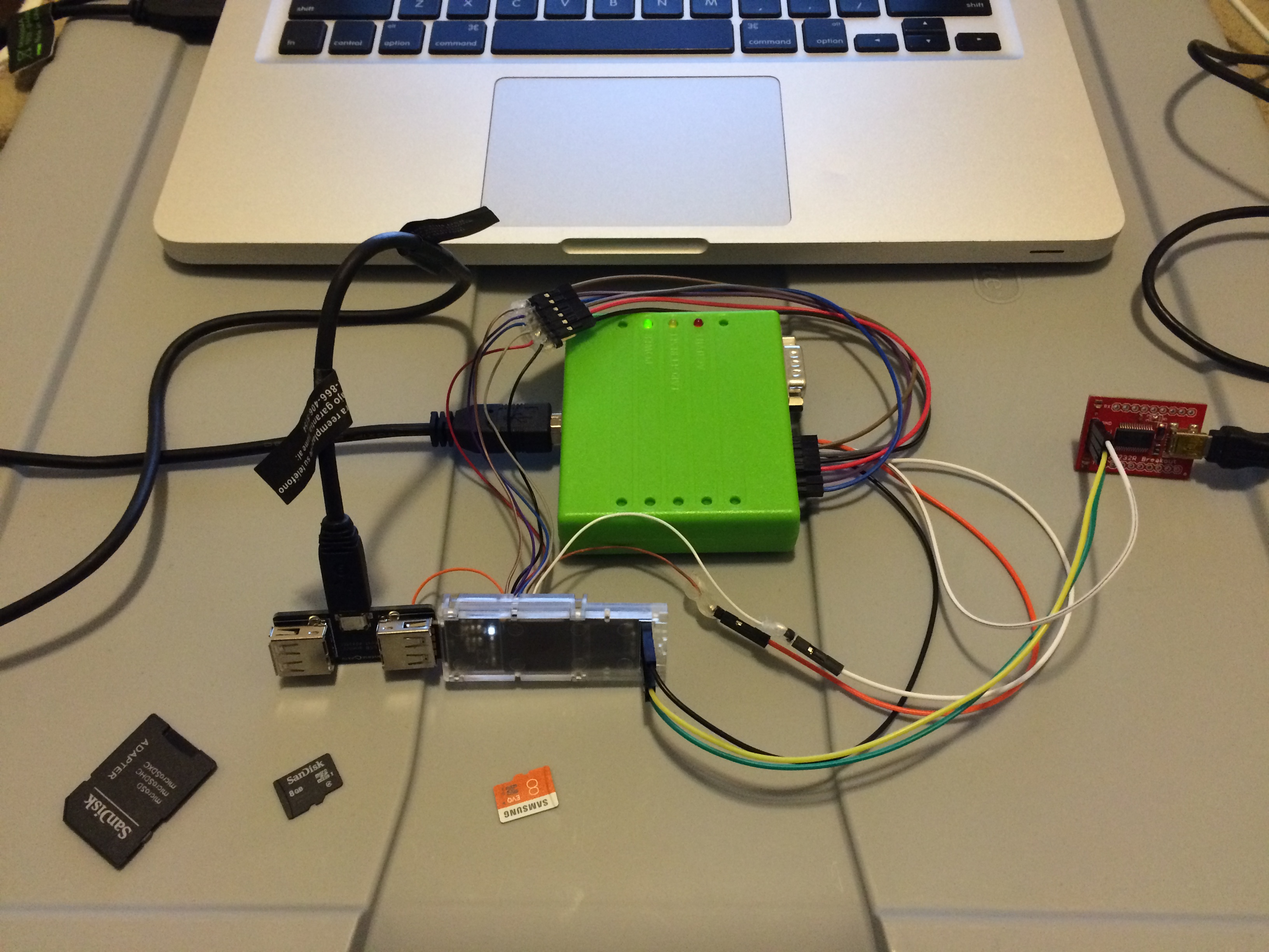 JTAG connected to Flyswatter 2, with UART breakout